
Advice
To design the quay wall, a design must be made. In general there are a huge number of options for the construction of the quay wall. The main question of this research is therefore:
"Which construction is suitable for the quay wall in the harbor of the design of the artificial island?"
To have this main question, the main question must be divided into sub questions, which are:
- How is the future taken into account in this draft?
- Which types of quay wall are applicable at this location?
- What are the vertical and horizontal loads on the quay wall?
- How is the phasing of this quay wall built?
In the first sub-question we look at aspects that will have an impact on the quay wall in the future. This concerns the increasing ship size and water level rise. The second sub-question concerns the type of quay wall that can be applied at this location. Here a trade-off is made between 13 different constructions. The 3rd sub-question is calculated which taxes exist in the quay wall and the thicknesses and networks are shit. Finally, we look at how the quay wall can be built. The detailed report of this quay wall can be found in X.
Construction type
The are 3 main construction included in the options wich are:
- Ground penetrating wall constructions
- Relief floor construction
- Overhang slope
These options were weighed against each other using assessment criteria. The main criteria are:
- Quality
- Costs
- Risks
After consideration, the combi wall came out with the best score. The MCA can be found in Annex x. The combi wall had a number of advantages which are:
- Suitable for large ground and water-retaining heights
- Large pile diameters available up to 3,4m
- High torge capacity and bending stifness
- Can absorb vrtical load well
Calculation
A number of values have been entered for the calculation in D-sheet. These are:
- Water level -1,04m NAP
- Ground level +5m NAP
- Length of the sheet pile From +5m NAP until -20m NAP
- Length of the piles From +5m NAP until -20m NAP
Phases
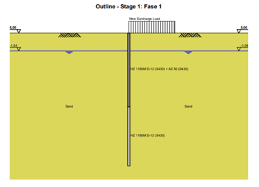
Phase 1
In phase 1 a load is applied tot the island side. This concerns the craned and other equipment for the realization of the pile and the sheet pile. The waterlevel is positioned at -1,04m NAP. The piles and the sheet pile will be installed in this phase. The calculation can be found in Annex X. In this phase there is relatively little distortion and moment present because the structure is the same for both sides. The only change is the 10kN/m upper weight on the island side. A visual representations can been seen in Figure 2: Phase 1.
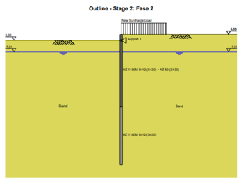
Phase 2
The combi wall is installed in pase 2. Now 2m is being excavated. The ground level on the water side is +3m NAP. A grout anchor is applied here. A visual representations can been seen in Figure 1: Phase 2.
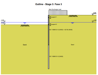
Phase 3
During this phase, the excavation will continue up to -3m NAP where the next anchor will be placed. A visual representations can been seen in Figure 3: Phase 3.
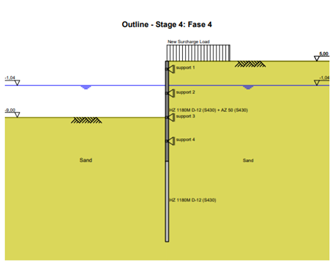
Phase 4
In phase 4 the excavation will continue up to -9m NAP here the next anchor will be placed. A visual representations can been seen in Figure 4: Phase 5.
Phase 5
Phase 5 is the last phase. Here the harbor is dug up to 15m NAP and the last anchor will be placed. The exact calculation can be found in Annex X.

Create Your Own Website With JouwWeb